FOUNDATION DRILLING MAGAZINE | December 2014 | View PDF
 Dallas, Texas like so many other major U.S. cities is in a constant state of road expansion and enhancement. You cannot drive on any major thoroughfare without passing by, and often being stuck in, rerouted lanes and/or the flow of construction equipment enroute from one jobsite or another. Such is the nature of life in a major city that is experiencing rapid growth. This holds true for the aging interstate highway system that was launched under the Eisenhower administration in 1956, as well as for the state highways and local connectors that serve the ever-expanding suburbs. While the funding for these kinds of projects is always a challenge there is no doubt that the necessity to address transportation needs to move people and goods is foremost on the agenda of every government entity. In the case of the Dallas/Fort Worth Metroplex, home to 6.6 million people, the march goes on. This is good news for geo-industry designers and constructors, and ultimately the traveling public.
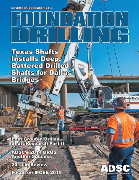
Many ADSC member companies are playing a key role in transportation projects throughout the U.S. and Canada. Such is the case in Dallas, Texas where Texas Shafts of Fort Worth is installing large, deep, cased, battered drilled shafts for one of the city’s new and “signature” bridge complexes, the “Margaret McDermott Pedestrian/Bicycle Bridge.”This work is part of the overall undertaking known as the “Horseshoe Project,” the massive $818 million dollar project that will upgrade the 1-30 and I-35 bridges that cross the Trinity River as well as the infamous “Mixmaster” in the southwestern part of the downtown area. As is the case in many major cities there tends to be one (or more…) highway junctions that cause a daily logjam of major proportions resulting in numerous delays, accidents, and literal heartburn for those who have no choice but to travel these essential byways.

Background
In the case of the work being undertaken in Dallas, which was developed in partnership with the Texas Department of Transportation (TxDOT), Texas Shafts President, Bo Walker noted that, “The project is of the Design/Build variety with Pegasus Link LLC (Balfour Beatty Infrastructure and Fluor Enterprises). The overall project, including the Margaret McDermott Bridge (MMD), for pedestrians and cyclists has been dubbed the ‘Horseshoe Project’ due to its Ushape. It has been given the highest priority because of the increased bridge maintenance cost.” The original plan is for the design and construction of three signature bridges. The first bridge, the Margaret Hunt Hill Bridge was designed by Spanish visionary architect and engineer Santiago Calatrava, and goes over the Trinity River in Dallas, Texas as part of the Trinity River Project. The Margaret Hunt Hill Bridge named for the philanthropist opened March 29, 2012. It is for vehicular traffic and
runs eastbound and westbound.
The second bridge, the Margaret McDermott Bridge was also designed by Calatrava and crosses over the Trinity. The MMD bridge is actually two bridges, one going eastbound and the other westbound with the I-30 Bridge in the center.
The city is in the midst of a downtown revitalization aimed at turning a once “empty feeling” downtown, after business hours, into a vital, pedestrian and cyclist-friendly metro area. The MMD bridges will provide pedestrian and bicycle access in and around downtown Dallas. The two $80 million pedestrian bridges, the foundations for which were installed by Texas Shafts is being con-
structed parallel to the new I-30 Bridge spanning the Trinity River. They will serve to enhance the city’s commitment to help make Dallas an attractive venue in which to live, work, and to visit.
Construction
Construction of the foundation for the bridge began in August 2013 and included drilled shafts socketed into shale. Most notable were forty-eight, 48 inch diameter, up to 88ft long shafts
Most notable were forty-eight, 48 inch diameter, up to 88ft long shafts installed on a 20 degree batter, using double walled sectional casing, oscillated down to bearing strata.
Walker added, “Gil Peel, President, American Equipment & Fabricating Corp. provided the technical engineering and support required to operate the specialized equipment at a 20 degree angle.” Texas Shafts used a Soilmec SR-65 drill rig* with a MGB 1500 casing oscillator that was mechanically and hydraulically attached to the base of the rig. In addition, a 20 degree engineered framework provided rigid support in order to keep the casing oscillator on the correct inclination while drilling took place. The oscillator and Leffer* segmental casing allowed the shafts to be advanced through the overburden materials. All the bridges for the Horseshoe project will include a total of 1,200 drilled shafts ranging from 36 inches to 108 inches in diameter adding up to approximately 100,000 linear feet. Despite the equipment challenges faced, the SR-65 production overall was excellent and instrumental in achieving the completion of this project ahead of schedule.
Subsurface Conditions
Subsurface conditions consisted of stiff fat clays underlain by layers of soft lean sandy clays, clayey sands, and sand with gravel. The sand with gravel layer typically was present above the shale. The shale is highly weathered near the top of the formation and becomes progressively stronger with depth. The shale is in the Eagle Ford Formation. It contains weakly cemented sand layers within the shale. Hard limestone layers and concretions are present intermittently throughout the shale. Groundwater was typically encountered approximately 20ft below the surface elevation.
Necessary Methods
The use of the oscillator and segmental casing was necessary in order to meet the technical requirements of the contract. The specifications required that the shaft excavation could not be advanced beyond the limits of the casing supported overburden. Unsupported or unshored excavation of the drilled shaft overburdens could have severe repercussions on the foundation system. The 20 degree slope frame was necessary to maintain the required batter. The specifications allowed only a one degree +/deviation from 20 degrees.
Special Considerations
Walker pointed out that, “Installation of the drilled shafts on a 20 degree batter required a more delicate touch than the traditional ‘driller’s mentality of the more power the better.” Equipment and tooling designed to function vertically do not necessarily operate efficiently on a 20 degree batter. Equipment and tools were structurally fatigued requiring constant care and field modifications. The segmental casing required a high level of maintenance and care in order to keep the casing installation running smoothly. Excessive wear on the screw connections was inevitable. It is important to note that maintaining plumbness of the shafts at a 20 degree batter presented a significant challenge and were critical to the success of the installation.
Special Challenges
Walker summarizes in detail the special challenges that this job created.
Casing
The use of sectional double-walled pipe that was designed for a plumb or vertical operation proved to be difficult requiring making connections suspended 10ft off the ground at a 20 degree angle. Additional connections were used during pipe installation to maintain slope. Connections of new pipe had to be made in a service shaft or “rat hole” due to the difficulty of making connections at a 20 degree angle. Rotary table clearance was critical with only one or two inches to spare when new sections were added.
Monitoring
Continuous monitoring, onboard and adjacent to the rig during operations, was required to prevent deviations. Accurate tolerance had to be maintained throughout the installation process.
Battered Shafts
Battered drill shafts of a smaller diameter have been installed in the past. To our knowledge this is the largest diameter cased hole at this great an angle to be installed. Many new methods were developed to allow the installation of these shafts.
Concrete Placement
As with any drilled shaft, concrete placement is a critical element. The batter of the shafts multiplies placement issues. Placing concrete in the absolute center of the shaft was not feasible. Flowability and rebar spacing were reviewed in order to design a proper concrete mix. Maximizing cage clearance to 6 inches allowed concrete to flow down the inside wall of the sectional casing.
Reinforcing Cages
In conventional drilled shafts reinforcement cages are designed to be hoisted into the air and then be lowered into the shaft excavation. In the case of battered shafts with this degree of slope it is not possible to use this method. It was therefore necessary to design and fabricate chair rollers that would allow the reinforcing cage to roll down the side walls of the shaft during placement and also to act as centering devices for the cage during concrete placement.
Designer Reluctance
Designers are reluctant to design drill shafts at extreme slopes due to the lack of experience and technology available to install the shafts. The MMD bridge foundations were installed using customized resources. Texas Shafts used existing technology and adapted it to the requirements of the project.
Alignment/Slope
Alignment and slope control was not difficult but much forethought and fabrication was applied before the project began. Alignment and slope control was monitored continually during installation and corrective action was minimal.
Groundwater
Ground water was sealed off from the drilled shaft exaction by seating the casing into the Eagle Ford shale. During drilling operations the casing was advanced through the overburdens while maintaining a soil “plug” at the cutting edge of the casing to eliminate water intrusion.
Double Wall
The double wall casing is for fabrication of the casing material. The double wall allows for male /female connections at the ends of the sections. The double wall pipe is no advantage for drilled shaft installation only in the fabrication of the pipe itself. Standard single wall casing would have been crushed by the force of the oscillator.
Conclusion
The cased drilled shafts installed on a 20 degree batter at the diameters and depths for this project may be a first of its kind, but not the first for Texas Shafts. They have been perfecting this construction method over time. Their work once again demonstrates the innovative abilities of drilled shaft foundation contractors who when presented with a daunting challenge find a way to rise (or drill down…) for the occasion.