REBAR CAGE FABRICATION AND POSITIONING
Drilled shaft foundations are constructed with a rebar cage inside to provide for strength and stability. The rebar cages are constructed to meet the needs of the design, both in rebar size and number required.
The Inspector must verify that the cages are fabricated, lifted and positioned properly and are within the allowable tolerances for “top of cage elevation” after positioning.
Quite often, post installation integrity testing will be specified and the access tubes for performing these test are part of the cage assembly.
Remember, it is imperative that the hole be clean and this should have been verified by the Inspector before the rebar cage is installed.
CAGE FABRICATION
The Inspector must verify that the cages are constructed in accordance with the plans and specifications, which includes verification of:
- Bar size
- Number of bars and condition
- Type and percentage of ties
- Diameter and length
- Couplers/splices
- Spacers and Standoff
CAGE LIFTING AND POSITIONING
Following fabrication of the cage, the Contractor will then lift the cage and lower it into the shaft.
Remember that prior to cage placement the Inspector verified the shaft depth and cleanliness.
It is important that the Contractor properly support the cage during lifting to avoid bending the cage so much that it is permanently distorted. If distorted to much, it won’t fit down the shaft without damaging the shaft walls.
Typically the cage will have standoffs on the bottom to maintain a certain clearance from the bottom of the hole and spacers on the outer edges to maintain a specified distance from the shaft walls.
This space between the shaft walls and the cage is to provide for the specified “concrete coverage”.
Once positioned in the shaft, the top of the cage is to be within a specified tolerance of the elevations shown in the plans.
In summary, the Inspector needs to verify and document:
- Lifting of the cage
- Positioning of the cage
- Top of cage elevation
- Couplers/splices
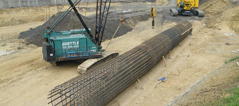
The photograph above shows the Inspector observing the lifting of the cage and the photo to the right, a cage lifted and ready to be placed in the hole.
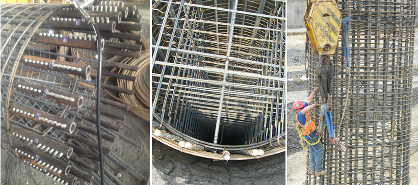
This photograph shows the cage being lowered into the hole. Notice that the standoffs and the side spacers are used to maintain the proper “coverage”.
Here is a photograph of the cage after being positioned in the hole. The Inspector needs to verify and document the “top of cage” elevation and if it is within the specified allowable construction tolerance.
ACCESS TUBES
Post installation integrity testing of drilled shafts has become very popular throughout the country. More economical than conventional load tests, some of the methods used provide a “picture” so to speak of the shaft in the ground.
To perform these types of test, access tubes, which permit lowering of instrumentation down into the shaft, must be installed on the cage prior to placing the cage in the hole.
The Inspector must verify and document that the tubes are of the length, diameter, and material specified, together with verifying they are secured to the cage and straight in accordance with the the project plans.
Shown here is an access tube inside the cage. Normally, they are installed on the inside of the cage, which helps protect them from damage.
Note the cap on the tube- this prevents debris or concrete from getting into the tube, which can prevent the instrumentation from going down the tubes.
DETERMINING CIRCUMFERENCES
Determining circumferences is one of the math computations the Inspector must be proficient in performing.
Typically the number of side spacers that help maintain the proper coverage distance, as discussed earlier in this Chapter, are generally determined by the cage circumference. The plans or specifications will typically indicate a certain number of spacers, based upon inches of circumference of the cage, be placed per level.
Circumference is the length of the outer boundary (perimeter) of a circular object.